the TinyBit game engine - part 7 - hardware
I have been holding off on this blog post for months. Partly because real life aggressively got in the way, and partly because I got distracted by another side project that consumed my remaining free time. I will write a post about that one eventually, assuming I do not get distracted by a third side project first.
This post covers the thing that actually makes TinyBit weird. You might think a simple custom game engine running Lua scripts is a dime a dozen in the hobbyist software space, and you would be right. But TinyBit is different. Not just because every line was typed by a human instead of hallucinated by a transformer model, but because it is designed to run on physical, custom-built hardware.
What kind of hardware? Glad you asked. That is literally the entire point of this write-up.
designing pcbs
My introduction to PCB design was a classic accident at university. We were supposed to build a small robotic learning platform for high schoolers and freshmen. My assigned role was software architecture. However, our team experienced an immediate and complete shortage of electrical engineers. Through process of elimination, I became the hardware guy. Fortunately, that first board was mostly just connecting traces between pre-made modules without any terrifying analog RF magic, so the prototype actually worked on the first try.
During my day job at Aquablu, history repeated itself. The company lacked a dedicated PCB designer, so I stepped up again. I ended up designing a series of production boards, each progressively more complex than the last, right up until the company hired someone with an actual degree in electrical engineering to fix my mistakes and take over.
Regardless of how I got here, those two experiences left me dangerously confident in my ability to spin custom circuit boards.
creating a gameboy in 2026
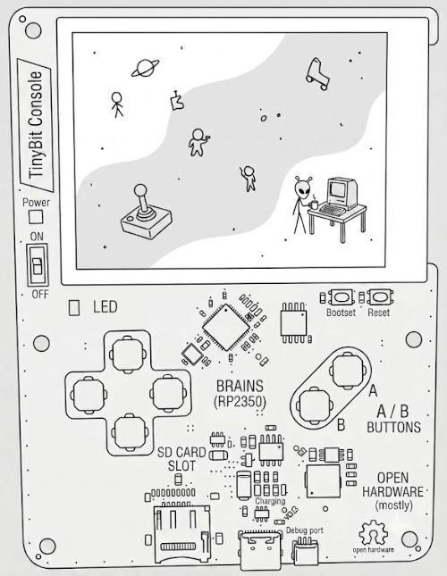
For the hardware, I wanted the exact same minimalist ethos as the software: no unnecessary fluff. Just distill the layout down to the quintessential handheld experience, which for me will always be the original Nintendo Game Boy.
Four directional buttons, A and B buttons, a power switch, and a small display. Instead of dealing with the mechanical nightmare of custom plastic edge connectors for physical cartridges, games load directly off a micro SD card.
the compute
Selecting the brain for a custom handheld comes down to two mutually exclusive hardware philosophies:
- CPU-based: These are miniature Linux machines. They have multiple cores running at gigahertz speeds, gobs of RAM, and dedicated GPUs. Audio, video pipelines, and file systems are trivial because the OS handles everything for you.
- MCU-based: Microcontrollers run exactly one program at a time, directly on the metal. They are conceptually simple, which paradoxically makes them a nightmare to build games for: no operating system, no native display controllers, no hardware audio mixing, no network stack, and zero file system abstraction out of the box.
If you are a sane engineer, you pick the Linux chip every single time.
I chose the microcontroller. TinyBit is meant to be small and constrained. Forcing myself onto a bare-metal chip keeps the scope tightly bounded and, as a nice side effect, makes the board schematic dramatically easier to draw.
That left the question of which specific silicon to solder down. Professionally, I spend most of my time wrestling with STM32 family chips. I have built hobby projects on ESP32s, and I grew up on ATmega chips back when Arduino was the only game in town. Here is how the candidates stacked up against my actual requirements:
- ESP32: Packed with horsepower, great hardware peripherals, built-in Wi-Fi and Bluetooth. Ideal on paper, but I personally despise the ESP-IDF toolchain and its opinionated high-level abstractions.
- ATmega: Nostalgic, but painfully underpowered. Not enough RAM, spi bus maxes out way too low for fluid framebuffers.
- ATxmega: Interesting middle ground, but I killed the only dev board I ever bought within ten minutes of opening the anti-static bag. Passed on this one.
- Raspberry Pi Pico: Technically worked, but memory constraints were razor-thin.
- STM32: Deep familiar territory, and I had plenty of dev boards in my desk drawers. To get the SPI bandwidth required for a fast display refresh rate, however, I would need a high-end chip package. Plus, FAT32 file system implementations on STM32 bare-metal are notoriously unpleasant to write.
Side note: designing your own bare-bones Arduino clone from scratch is practically a rite of passage for embedded devs. Mine was an ATmega328P, a 16MHz crystal, two 22pF capacitors, and a whole lot of wire jumpers. Highly recommended if you enjoy pain.
As detailed in part 5 - memory, the engine requires roughly 420KB of usable RAM just to exist. Driving a 240x240 pixel display at 60Hz requires an SPI clock running around 60MHz. Finally, the CPU needs enough clock cycles to execute the Lua interpreter, synthesize audio buffers, and render the frame buffer without dropping frames.
Yes, I am aware this creates a circular dependency. The memory budget depends on the hardware, but the hardware selection depends on the memory budget. Welcome to embedded systems development, where we regularly build the airplane mid-flight.
Filtering through these constraints left only two real contenders: the ESP32 and the newer RP2350 from Raspberry Pi. The ESP32 easily wins the raw specs contest, but again, I dislike writing code for it. The RP2350 barely meets the performance threshold, but the developer experience is fantastic. Fun won.
the RP2350
The RP2350 is a delightful piece of silicon for hobbyists. The SDK feels like an upgraded Arduino environment rather than an enterprise C++ framework designed to make you suffer.
Look at a simple GPIO toggle in the Pico SDK:
#include "pico/stdlib.h"

int main(void) {
    gpio_init(25);
    gpio_set_dir(25, GPIO_OUT);
    while (true) {
        gpio_put(25, 1);
        sleep_ms(500);
        gpio_put(25, 0);
        sleep_ms(500);
    }
}
Now look at the equivalent boilerplate required by ESP-IDF:
#include "driver/gpio.h"
#include "freertos/FreeRTOS.h"
#include "freertos/task.h"

void app_main(void) {
    gpio_config_t cfg = {
        .pin_bit_mask = 1ULL << 2,
        .mode = GPIO_MODE_OUTPUT,
        .pull_up_en = GPIO_PULLUP_DISABLE,
        .pull_down_en = GPIO_PULLDOWN_DISABLE,
        .intr_type = GPIO_INTR_DISABLE,
    };
    gpio_config(&cfg);

    while (1) {
        gpio_set_level(2, 1);
        vTaskDelay(pdMS_TO_TICKS(500));
        gpio_set_level(2, 0);
        vTaskDelay(pdMS_TO_TICKS(500));
    }
}
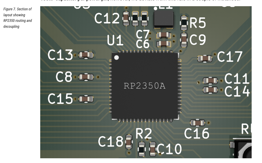
Raspberry Pi also published an exceptionally clear hardware design guide. It is thoroughly documented and treats the reader like an adult who just wants to layout a board properly.
The chip also includes hardware features like PIO (Programmable I/O), which lets you execute tiny assembly state machines on the I/O pins independently of the main CPU cores. It also has hardware interpolators that execute add, shift, and mask operations in a single clock cycle, which is ridiculously useful for custom rendering tricks.
designing the PCB
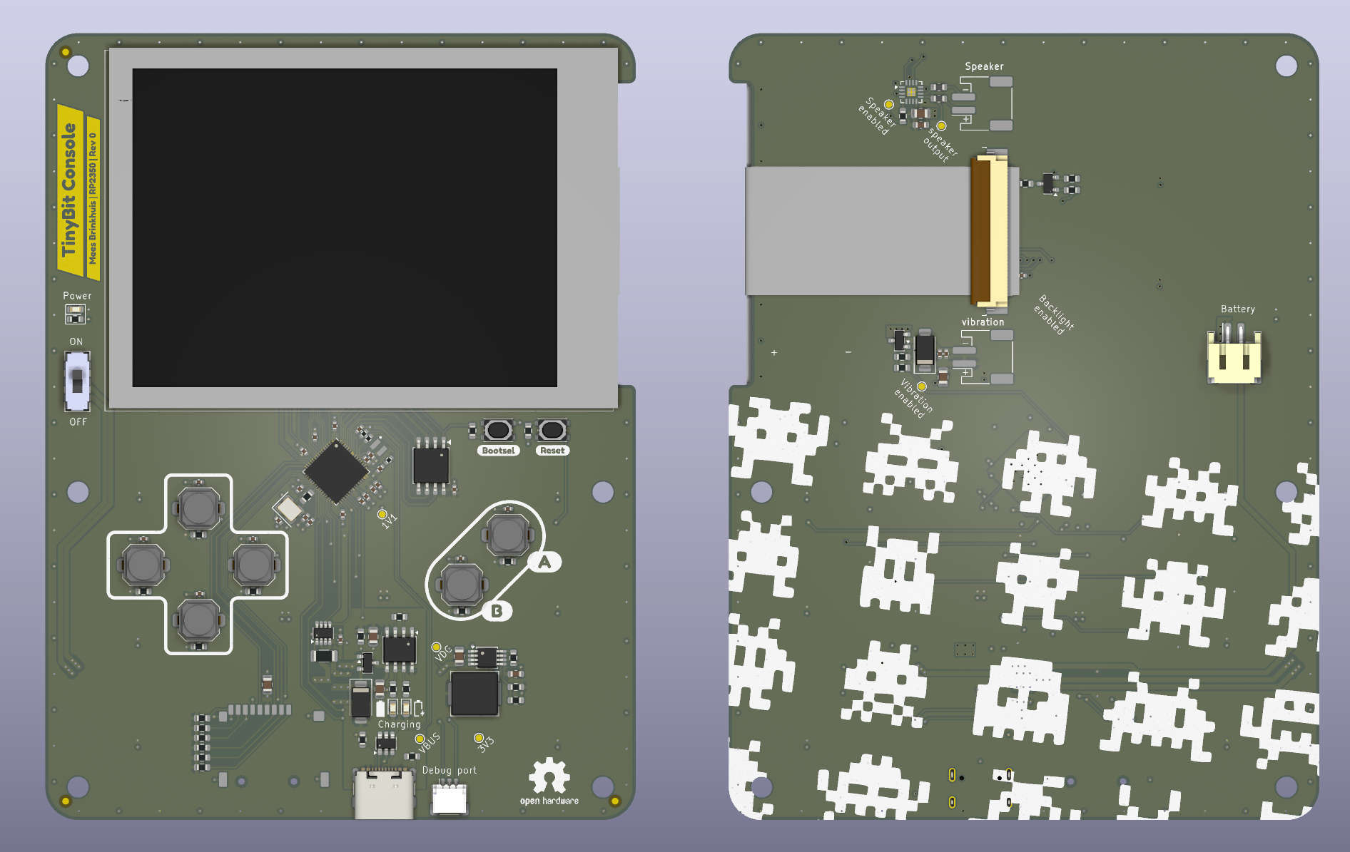
Using the reference schematics, I laid out the core system: the RP2350 MCU, external flash memory, a crystal oscillator, decoupling capacitors, and power regulation. High-frequency crystals require strict trace routing and specific load capacitor matching if you want the clock to actually oscillate, so I followed the reference layout down to the millimeter.
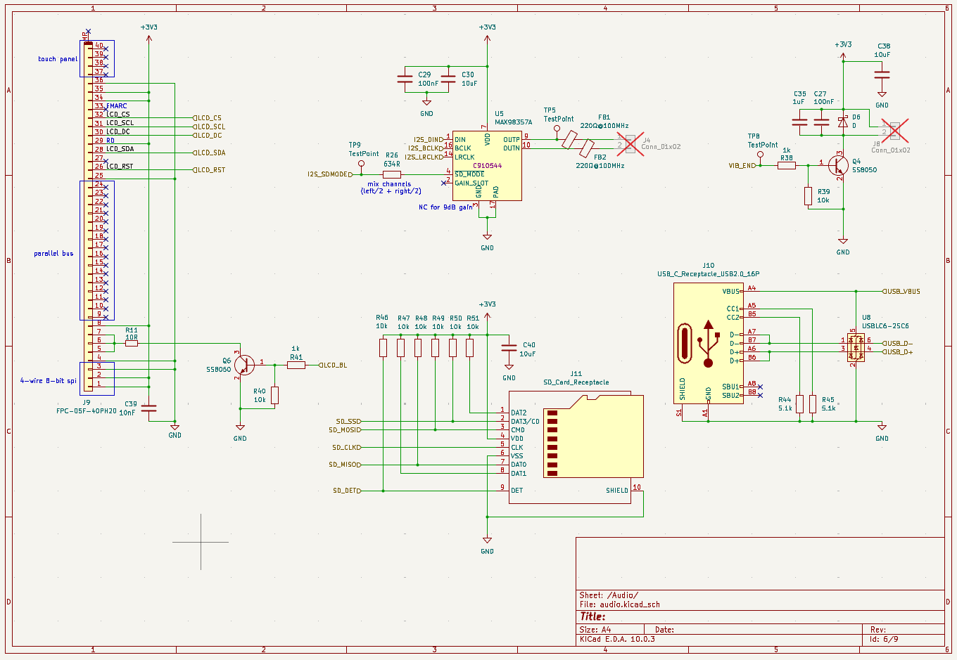
For the display, I chose a 3.2-inch IPS TFT panel running 320x240 pixels with a flat flexible cable (FFC). It uses an ST7789 driver IC. Thanks to the RP2350's PIO state machines, pushing display data over SPI required minimal CPU overhead.
Power handling required balancing two sources: a small single-cell LiPo battery glued to the back, and 5V power from the USB-C port. I needed a circuit that could charge the battery while plugged in, but also run the system directly off USB power if no battery was connected at all.
The solution was using the intrinsic body diode of a MOSFET. When USB power is missing, the gate is pulled low, allowing current to flow from the battery to the system. When USB is plugged in, the gate rises, turning off the MOSFET and preventing the 5V line from dumping raw current directly into the battery cell, forcing power through the dedicated TP4056 charging IC instead.
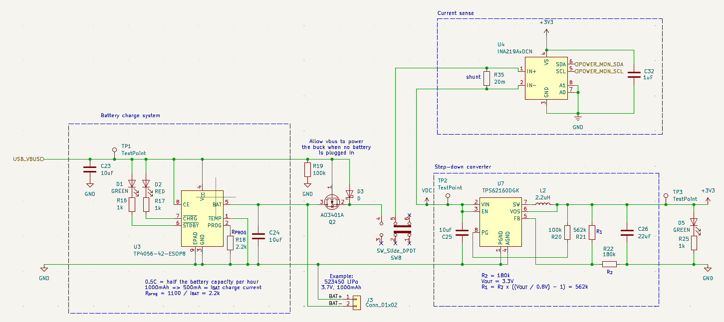
A step-down buck converter steps the variable input voltage down to a clean 3.3V rail to feed the RP2350, screen, audio amp, micro SD card, and a haptic vibration motor.
Routing all those signals together produced this final PCB layout:
prototyping
Ordering a raw PCB design without testing the schematic on real hardware first is a great way to throw money directly into the trash.
I wired up a massive breadboard prototype: a Pico board, the target TFT display, a breakout board for the I2S audio amplifier, and an SD card reader module. It looked like a bomb prop from an action movie, but it worked.
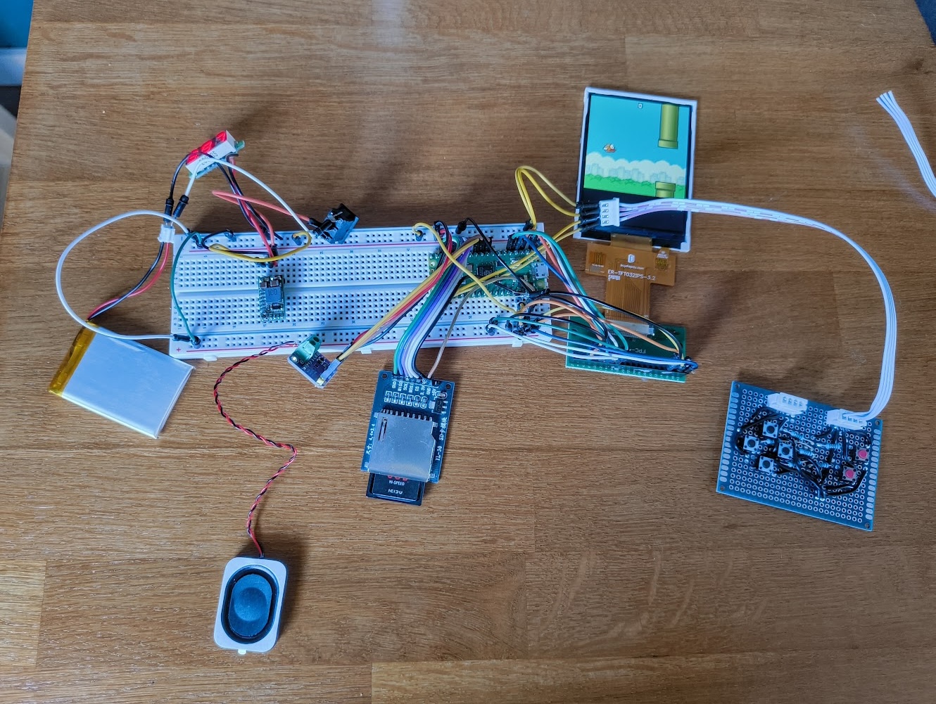
This mess was my proof of concept. It let me verify screen frame rates, profile Lua execution speed, and measure real-world current draw from the battery. Everything passed performance targets. Time to build the real thing.
Naturally, I opted to hand-assemble the board myself rather than pay the factory assembly fee. I ordered bare boards from Aisler and raw component reels from LCSC.
Here is the board after forty-five painful minutes of placing tiny 0402 surface-mount components with tweezers. Once everything was aligned, I transferred the board to a hot plate and used a hot air station to reflow the solder paste.
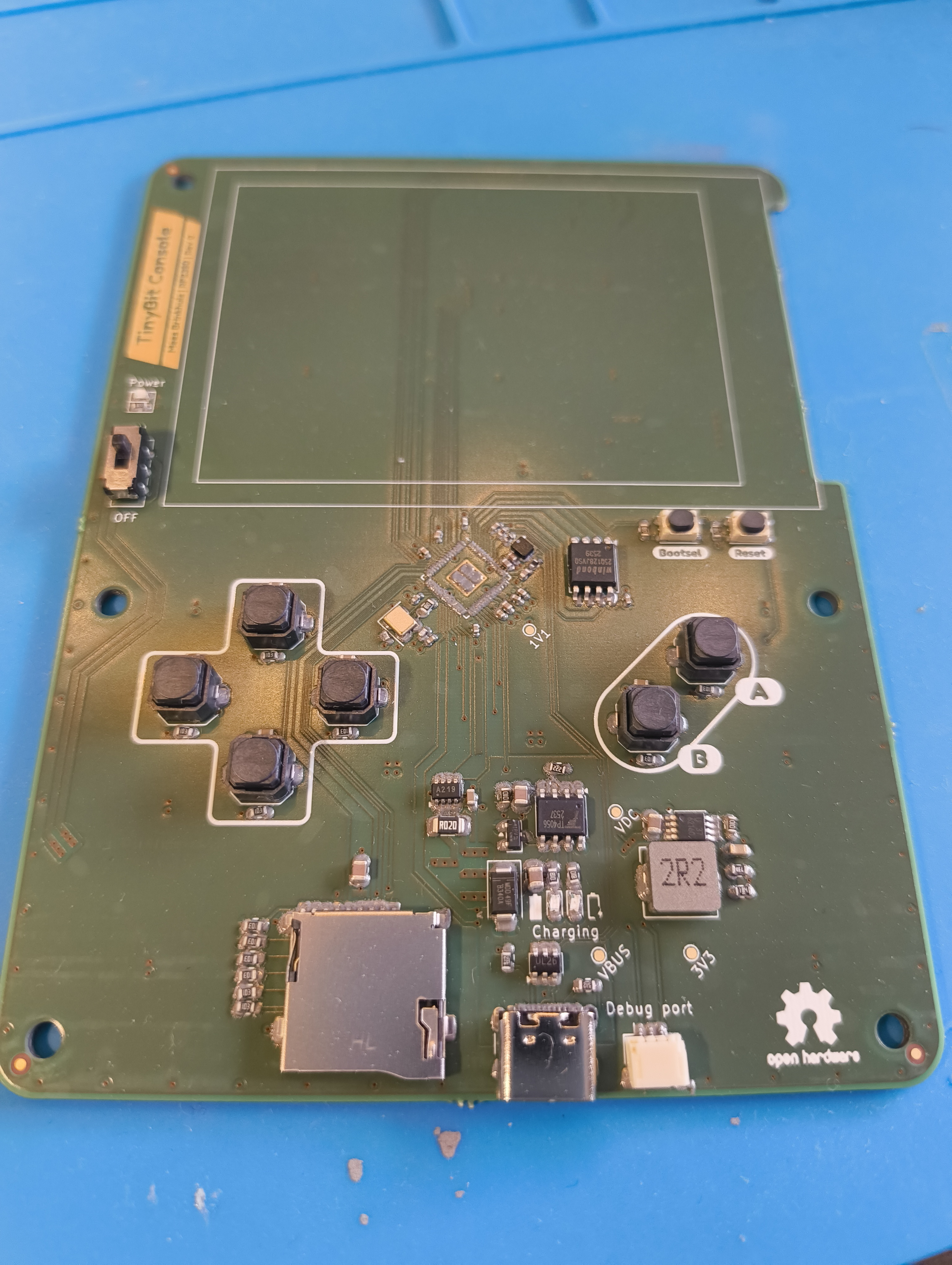
The initial reflow left me with a completely dead board. Quad Flat No-lead (QFN) chip packages are notorious for hidden solder bridges underneath the silicon body. I spent an entire afternoon applying flux, reheating the chip, and scrubbing tiny solder bridges off the board.
Eventually, it booted. Sort of.
Two minor oversights ruined the celebration: I ordered a top-contact FFC connector instead of a bottom-contact one, rendering the screen pinout backwards. Additionally, I misread the pinout diagram on the mechanical power switch, so turning the switch "ON" permanently grounded the enable line.
At least now I am feeling certain that my next iteration will be fully correct. Which I will then order assembled, money be damned.
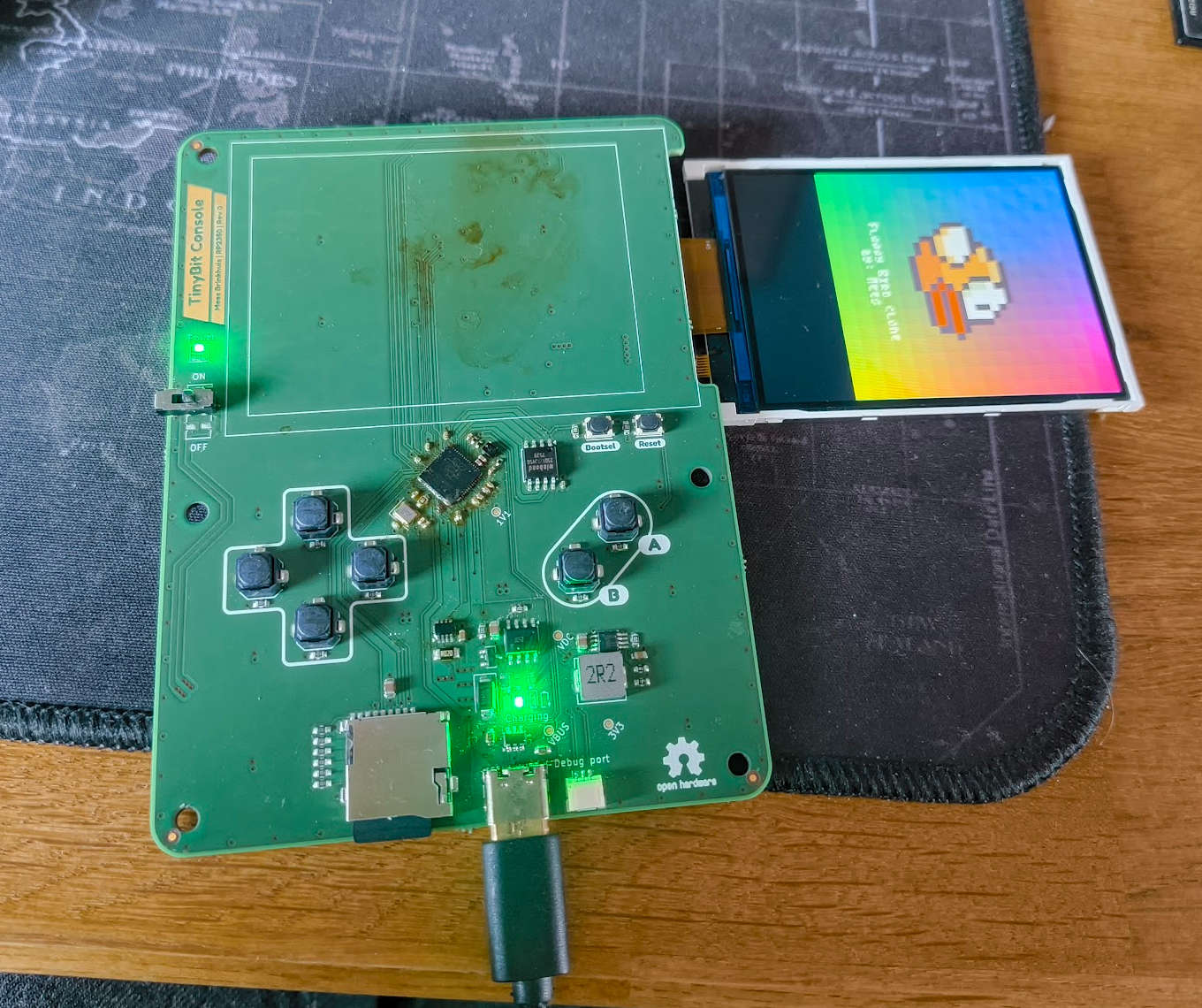
That brings the project up to date. House renovations recently banished me from my home workbench for a few months, putting physical assembly on pause. The updated PCB Gerber files are ready, and I am doing one last review pass before hitting the order button.
Building custom hardware to run a custom game engine is easily one of the most rewarding engineering projects I have tackled. Writing the software, routing the traces, and soldering the silicon feels like building an early 1990s gaming handheld from first principles. In a software landscape increasingly dominated by automated code generators, having a physical device on your desk that you built entirely by hand is deeply satisfying.
Part 8 will feature the fully assembled revision two hardware, along with open-source board files so you can build your own TinyBit handheld. Assuming I do not get distracted again.